Hardware Information
This page is the hardware reference for Blade 3: its main components and where each connector sits. For the details of a specific connector, including its pin assignments, and how to use it, see the corresponding page in Hardware Usage.
For the full specifications, see Key Parameters.
Block Diagram
Chip Block Diagram
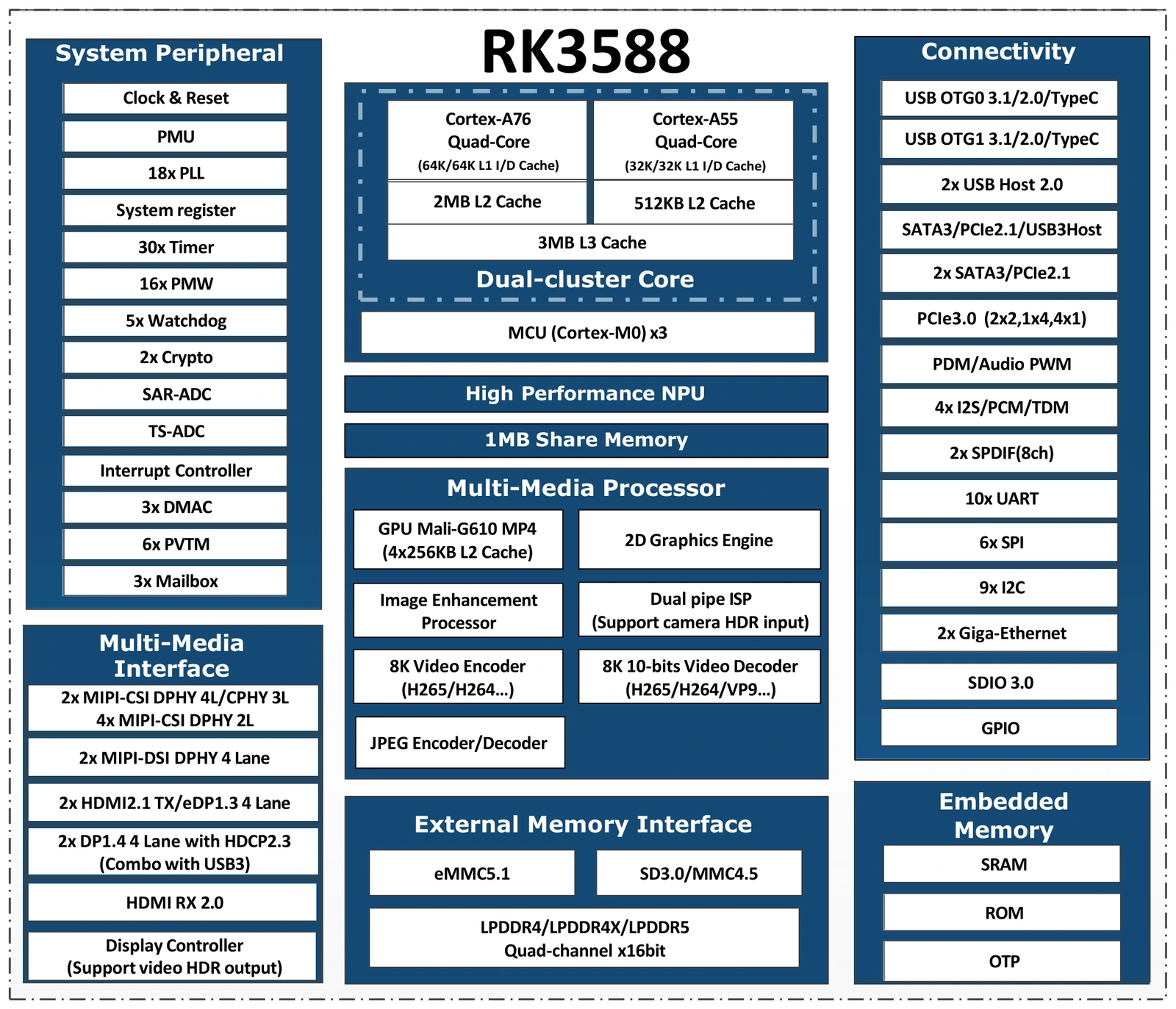
Figure 1. RK3588 block diagram. Source: Rockchip RK3588 Brief Datasheet
System Block Diagram
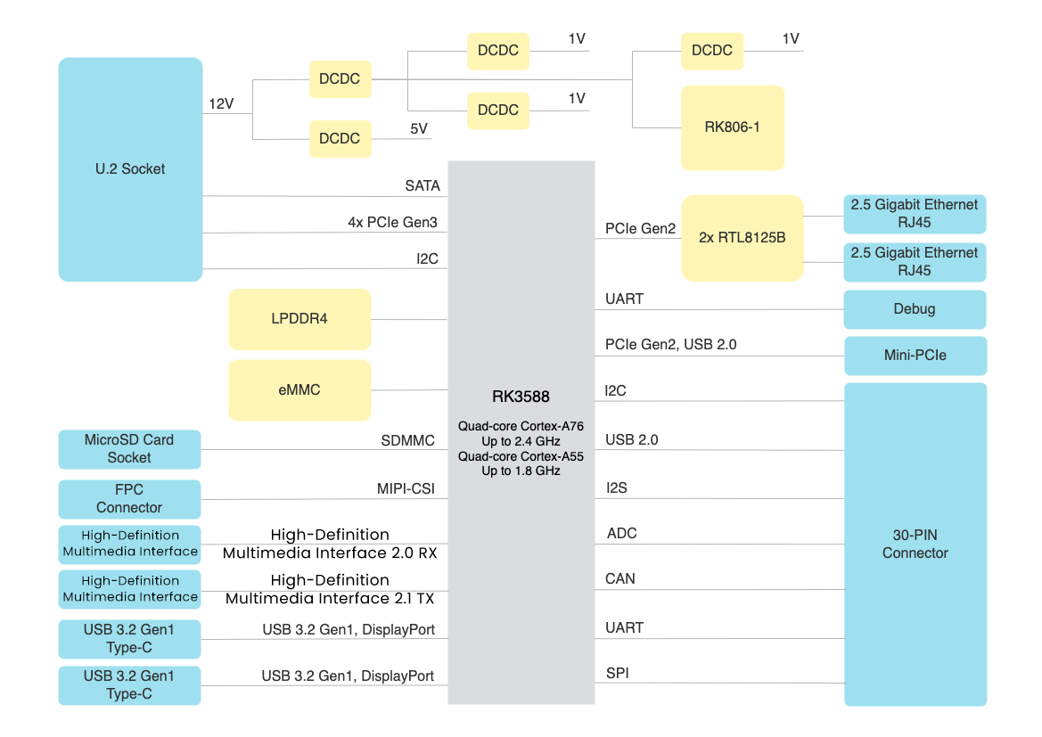
Figure 2. System block diagram of Blade 3
Interface Information
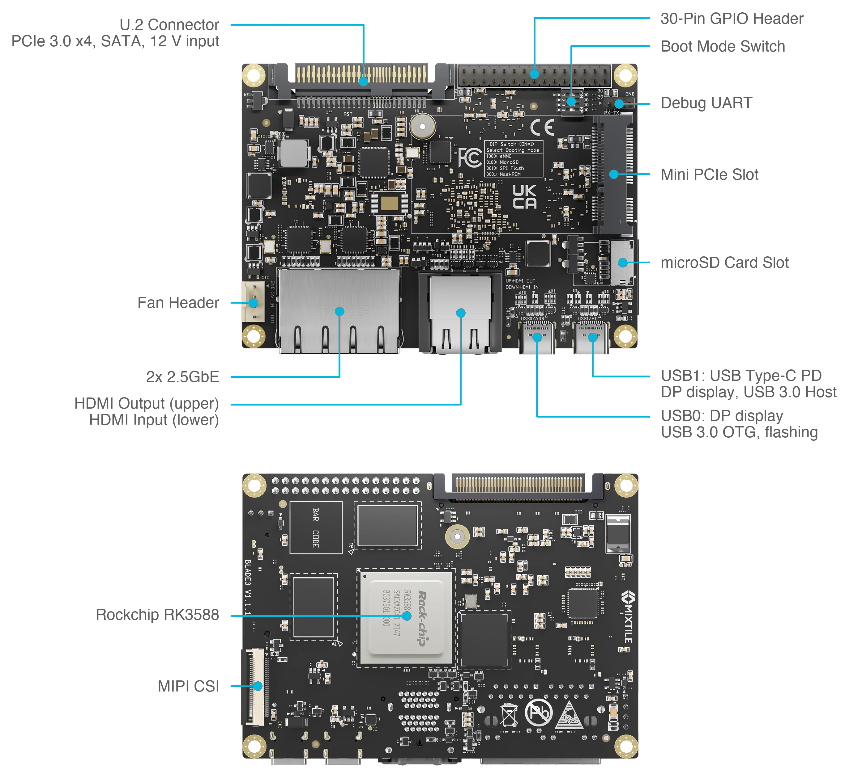
Figure 3. Connector layout, top and bottom
| Interface | Qty | Description |
|---|---|---|
| Rockchip RK3588 | 1 | SoC, on the bottom side |
| 30-pin Header | 1 | GPIO, I²C, I²S, SPI, CAN, ADC, PWM, USB 2.0 |
| Mini PCIe | 1 | PCIe 2.0 and USB 2.0, for Wi-Fi, cellular and similar modules |
| MIPI-CSI | 1 | Four-lane camera connector, on the bottom side |
| U.2 | 1 | Edge connector with PCIe 3.0 x4, SATA 3.0 and 12 V input |
| Fan | 1 | Four-pin 5 V fan connector |
| Debug UART | 1 | Three-pin serial console header |
| Boot mode switch | 1 | Four positions that select the boot device. Position 1: eMMC, 2: microSD, 3: SPI flash, 4: MaskROM |
| microSD card slot | 1 | SD 3.0 |
| USB-C | 2 | USB0/ADB: OTG, DisplayPort, flashing. USB1/PD: power input, DisplayPort |
| HDMI | 2 | Upper: HDMI 2.1 output. Lower: HDMI 2.0 input |
| 2.5 Gigabit Ethernet | 2 | RJ45 |
| Power LED | 1 | Lights up when the board is powered |
Dimensions
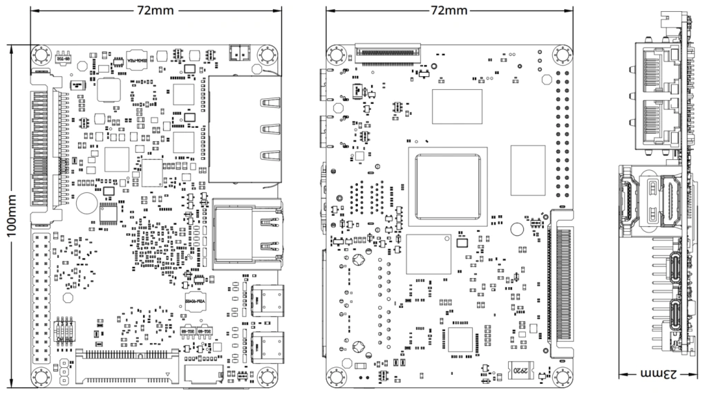
Figure 4. Dimensions of Blade 3
The board is 100 x 72 mm, in the 2.5-inch Pico-ITX form factor. Each corner has a 3.2 mm mounting hole for M3 screws.