Debug UART
The debug UART is a three-pin header that carries the serial console. It is next to the Mini PCIe slot, and pin 1 is marked with a triangle on the board.
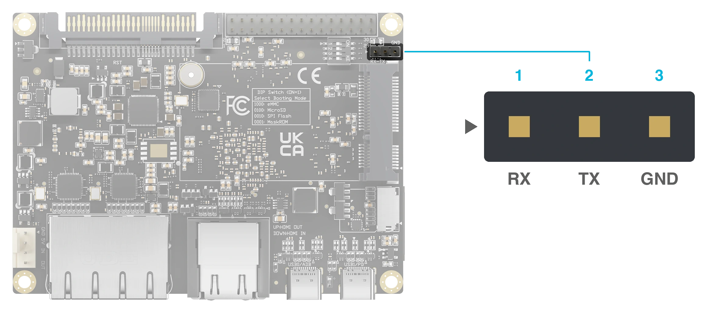
Figure 1. The debug UART header
Specifications
- Three pins: RX, TX, GND
- 1500000 baud, 8N1, no flow control
Pin Assignments
| Pin# | PinName | PinType | Input/Output | Signal Description |
|---|---|---|---|---|
| 1 | UART2_RX_M0_DEBUG | signal | Input | UART2 Receive Data for debug |
| 2 | UART2_TX_M0_DEBUG | signal | Output | UART2 Transmit Data for debug |
| 3 | GND | signal | NA | Power and signal reference ground |
Wiring
Connect a USB to TTL converter's GND to pin 3, its TXD to RX (pin 1), and its RXD to TX (pin 2). Do not connect the converter's VCC.
For the complete serial-console connection procedure, see Connect to Blade 3.