Mini PCIe
Blade 3 has one Mini PCIe socket on the top of the board. It carries both PCIe 2.0 and USB 2.0 signals, so it accepts modules that use either interface, such as Wi-Fi cards.

Figure 1. Mini PCIe slot of Blade 3
Specifications
- Standard 52-pin Mini PCIe socket
- Accepts 30 × 52 mm modules
- Carries PCIe 2.0 and USB 2.0
- 3.3 V supply to the module, up to 3 A across all its power pins
- No SIM card signals: pins 8, 10, 12, 14 and 16 are not connected
Pin Assignments
| Pin# | PinName | PinType | Input/Output | Signal Description |
|---|---|---|---|---|
| 1 | MINIPCIE20_WAKEN_3V3_L | signal | Input | Wake up signal from mini-PCIe device |
| 2 | VCC3V3_MINIPCIE | Power | Output | Power supply for mini-PCIe device,3.3V output MAX 3A in all pins |
| 3 | NC | float | NA | Not connected to this pin |
| 4 | GND | Power | NA | Power and signal reference ground |
| 5 | NC | float | NA | Not connected to this pin |
| 6 | NC | float | NA | Not connected to this pin |
| 7 | MINIPCIE20_CLKREQN_3V3_L | signal | Input | PCIe2.0 Channel Reference clock request |
| 8 | NC | float | NA | Not connected to this pin |
| 9 | GND | Power | NA | Power and signal reference ground |
| 10 | NC | float | NA | Not connected to this pin |
| 11 | PCIE20_2_REFCLKN | LVDS | Output | PCIe20 Port2 differential clock Negative |
| 12 | NC | float | NA | Not connected to this pin |
| 13 | PCIE20_2_REFCLKP | LVDS | Output | PCIe20 Port2 differential clock Positive |
| 14 | NC | float | NA | Not connected to this pin |
| 15 | GND | Power | NA | Power and signal reference ground |
| 16 | NC | float | NA | Not connected to this pin |
| 17 | NC | float | NA | Not connected to this pin |
| 18 | GND | Power | NA | Power and signal reference ground |
| 19 | NC | float | NA | Not connected to this pin |
| 20 | W_DISABLEN | signal | Output | PCIE device wireless disable |
| 21 | GND | Power | NA | Power and signal reference ground |
| 22 | MINIPCIE20_PERSTN | signal | Output | PCIE device reset |
| 23 | PCIE20_2_RXN | LVDS | Input | PCIe20 receive differential Negative |
| 24 | VCC3V3_MINIPCIE | Power | Output | Power supply for mini-PCIe device,3.3V output MAX 3A in all pins |
| 25 | PCIE20_2_RXP | LVDS | Input | PCIe20 receive differential Positive |
| 26 | GND | Power | NA | Power and signal reference ground |
| 27 | GND | Power | NA | Power and signal reference ground |
| 28 | NC | float | NA | Not connected to this pin |
| 29 | GND | Power | NA | Power and signal reference ground |
| 30 | NC | float | NA | Not connected to this pin |
| 31 | MINIPCIE20_TX_N | LVDS | Output | PCIe20 transmit differential Negative |
| 32 | NC | float | NA | Not connected to this pin |
| 33 | MINIPCIE20_TX_P | LVDS | Output | PCIe20 transmit differential Positive |
| 34 | GND | Power | NA | Power and signal reference ground |
| 35 | GND | Power | NA | Power and signal reference ground |
| 36 | MINIPCIE_USB_DM | LVDS | BI | USB20 HOST Port1 Data Minus |
| 37 | GND | Power | NA | Power and signal reference ground |
| 38 | MINIPCIE_USB_DP | LVDS | BI | USB20 HOST Port1 Data Plus |
| 39 | VCC3V3_MINIPCIE | Power | Output | Power supply for mini-PCIe device,3.3V output MAX 3A in all pins |
| 40 | GND | Power | NA | Power and signal reference ground |
| 41 | VCC3V3_MINIPCIE | Power | Output | Power supply for mini-PCIe device,3.3V output MAX 3A in all pins |
| 42 | NC | float | NA | Not connected to this pin |
| 43 | GND | Power | NA | Power and signal reference ground |
| 44 | NC | float | NA | Not connected to this pin |
| 45 | NC | float | NA | Not connected to this pin |
| 46 | NC | float | NA | Not connected to this pin |
| 47 | NC | float | NA | Not connected to this pin |
| 48 | NC | float | NA | Not connected to this pin |
| 49 | NC | float | NA | Not connected to this pin |
| 50 | GND | Power | NA | Power and signal reference ground |
| 51 | NC | float | NA | Not connected to this pin |
| 52 | VCC3V3_MINIPCIE | Power | Output | Power supply for mini-PCIe device,3.3V output MAX 3A in all pins |
Install a Module
- Shut down Blade 3 and disconnect the power adapter.
- Line up the notch in the module's edge with the key in the socket.
- Insert the module into the socket at a 30-degree angle.
- Press the module down flat, and secure it with the screw.
- If the module has antenna connectors, connect the required antennas before using the module.
- Reconnect the power adapter. Blade 3 starts up.
warning
Do not force the module into the socket.
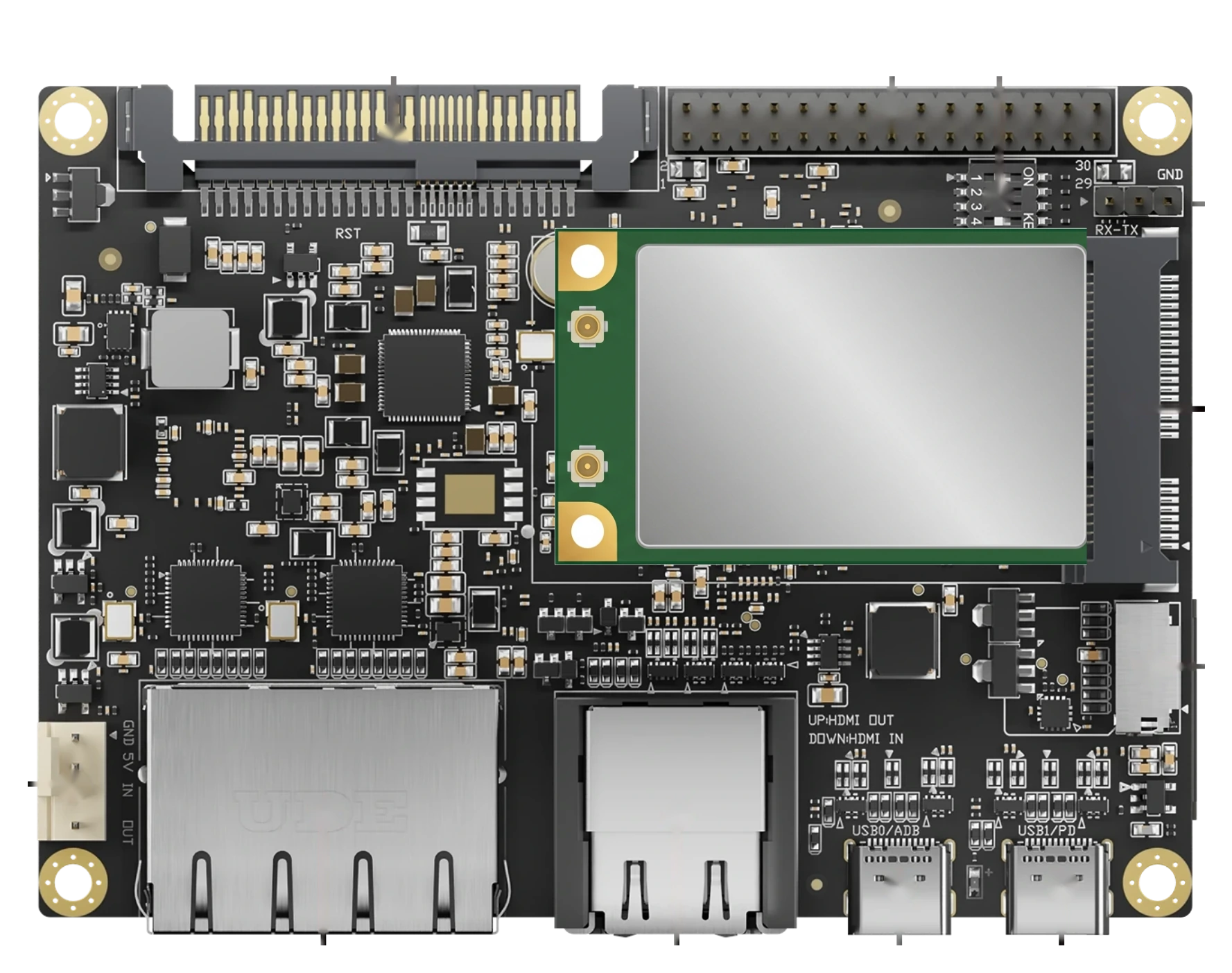
Figure 2. Mini PCIe module installed in the Blade 3 socket.
Verify the Module
Log in to the board, see Connect to Blade 3, and check that the module is listed:
-
A module that uses PCIe appears in the output of
lspci:Blade 3lspci -
A module that uses USB appears in the output of
lsusb:Blade 3lsusb
To work, the module also needs a Linux driver and, for many modules, firmware in the running system.