MIPI-CSI
Blade 3 has one four-lane MIPI-CSI camera connector, on the bottom side of the board near the edge.
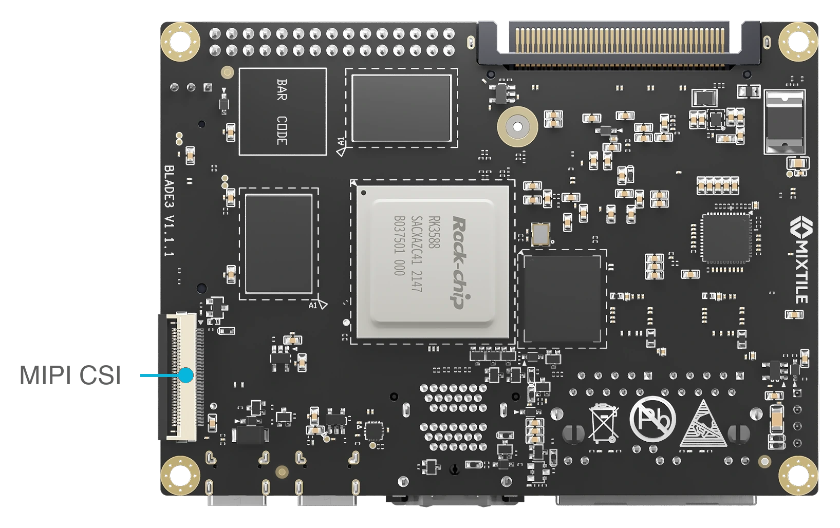
Figure 1. MIPI-CSI camera connector on the bottom side of Blade 3
note
The current Mixtile OS image does not configure a camera pipeline for this connector by default.
Specifications
- 30 pins
- MIPI CSI0 receiver: four data lanes and one clock lane
- Camera control signals: I²C, reset, power-down and master clock
- 3.3 V and 5 V supply outputs for the camera module
Pin Assignments
| Pin# | PinName | PinType | Input/Output | Signal Description |
|---|---|---|---|---|
| 1 | GND | Power | NA | Power and signal reference ground |
| 2 | MIPI_CSI0_RX_D0N | LVDS | Input | MIPI CSI0 receive differential data lane 0 Negative |
| 3 | MIPI_CSI0_RX_D0P | LVDS | Input | MIPI CSI0 receive differential data lane 0 Positive |
| 4 | GND | Power | NA | Power and signal reference ground |
| 5 | MIPI_CSI0_RX_D1N | LVDS | Input | MIPI CSI0 receive differential data lane 1 Negative |
| 6 | MIPI_CSI0_RX_D1P | LVDS | Input | MIPI CSI0 receive differential data lane 1 Positive |
| 7 | GND | Power | NA | Power and signal reference ground |
| 8 | MIPI_CSI0_RX_CLK0N | LVDS | Input | MIPI CSI0 receive differential Clock 0 Negative |
| 9 | MIPI_CSI0_RX_CLK0P | LVDS | Input | MIPI CSI0 receive differential Clock 0 Positive |
| 10 | GND | Power | NA | Power and signal reference ground |
| 11 | MIPI_CSI0_RX_D2N | LVDS | Input | MIPI CSI0 receive differential data lane 2 Negative |
| 12 | MIPI_CSI0_RX_D2P | LVDS | Input | MIPI CSI0 receive differential data lane 2 Positive |
| 13 | GND | Power | NA | Power and signal reference ground |
| 14 | MIPI_CSI0_RX_D3N | LVDS | Input | MIPI CSI0 receive differential data lane 3 Negative |
| 15 | MIPI_CSI0_RX_D3P | LVDS | Input | MIPI CSI0 receive differential data lane 3 Positive |
| 16 | GND | Power | NA | Power and signal reference ground |
| 17 | MIPI_CAM_PWM2 | signal | Output | PWM2 for LENS |
| 18 | NC | float | NA | Not connected to this pin |
| 19 | VCC_3V3_S0 | Power | Output | Power supply for sensor board,3.3V output |
| 20 | MIPI_CAM_RESETN | signal | Output | GPIO out for sensor reset |
| 21 | NC | float | NA | Not connected to this pin |
| 22 | MIPI_CAM_PDN | signal | Output | GPIO out for sensor power down |
| 23 | I2C3_SDA_M3_MIPI | signal | BI | I2C3 Bus data |
| 24 | I2C3_SCL_M3_MIPI | signal | Output | I2C3 Bus clock |
| 25 | GND | Power | NA | Power and signal reference ground |
| 26 | MIPI_CAM2_CLK_M1_3V3 | signal | Output | Camera Master clock output |
| 27 | GND | Power | NA | Power and signal reference ground. |
| 28 | VCC_5V0 | Power | Output | Power supply for sensor board, 5V output |
| 29 | VCC_5V0 | Power | Output | Power supply for sensor board, 5V output |
| 30 | VCC_5V0 | Power | Output | Power supply for sensor board, 5V output |