Hardware Information
This page is the hardware reference for Core 3588E: what is on the module, what the carrier board adds, and where each connector sits. For how to use a specific interface, see the corresponding page in Hardware Usage.
For the full specifications, see Key Parameters.
Module and Carrier Board
Core 3588E is only the module. It holds the RK3588, the memory, the eMMC, the power management, the clocks, the real-time clock and the Ethernet PHY. All of its signals, and its 5 V power input, pass through the 260-pin SO-DIMM edge connector.
Every port you plug a cable into is on the carrier board. The carrier board decides which of the module's interfaces you can reach, and with which connector.
Module Block Diagram
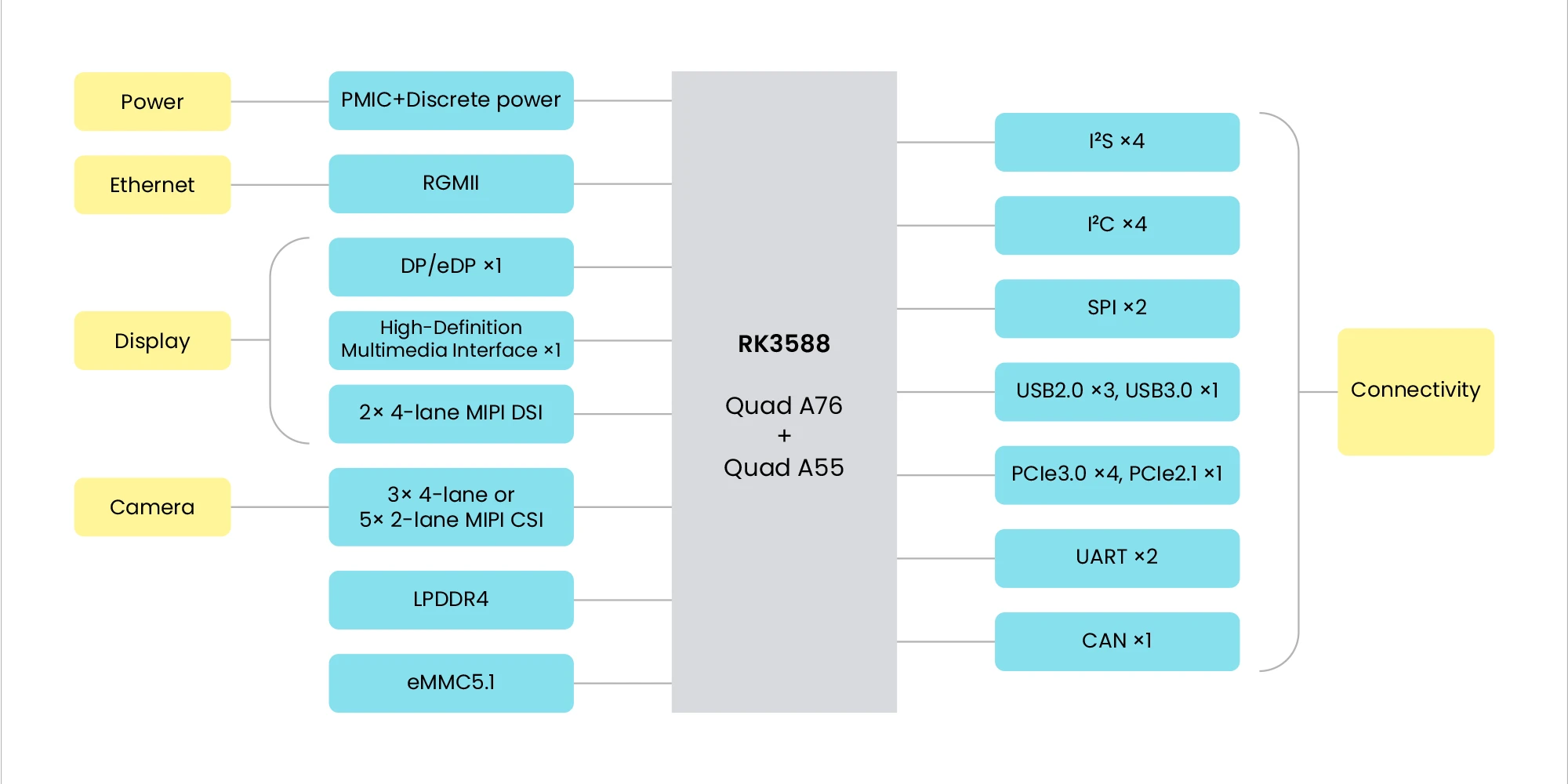
Figure 1. Block diagram of Core 3588E
Module Interfaces
The module brings these interfaces to the edge connector. The pin of each signal is in 260-pin Connector.
| Interface | Description |
|---|---|
| Power | 5 V input, and the power-on and reset signals for the carrier board |
| Display | One HDMI output and one DisplayPort output |
| MIPI CSI | Camera inputs CSI0 to CSI4 |
| MIPI DSI | One two-lane display output |
| PCIe | PCIe 3.0 x4 and PCIe 2.1 x1 |
| USB | One USB 3.0 port and three USB 2.0 ports |
| Ethernet | Gigabit Ethernet, with the PHY on the module |
| UART | Debug UART and two UARTs with flow control |
| I²C, SPI, I²S, GPIO | For expansion headers on the carrier board |
| CAN | One CAN controller |
| SD | One SD card interface |
| RTC | Real-time clock on the module, with a backup battery input |
Leetop A206 Carrier Board
This documentation uses the Leetop A206, a carrier board for the Jetson TX2 NX.
Connector Locations
The numbers in Figures 2 to 4 match the table below.
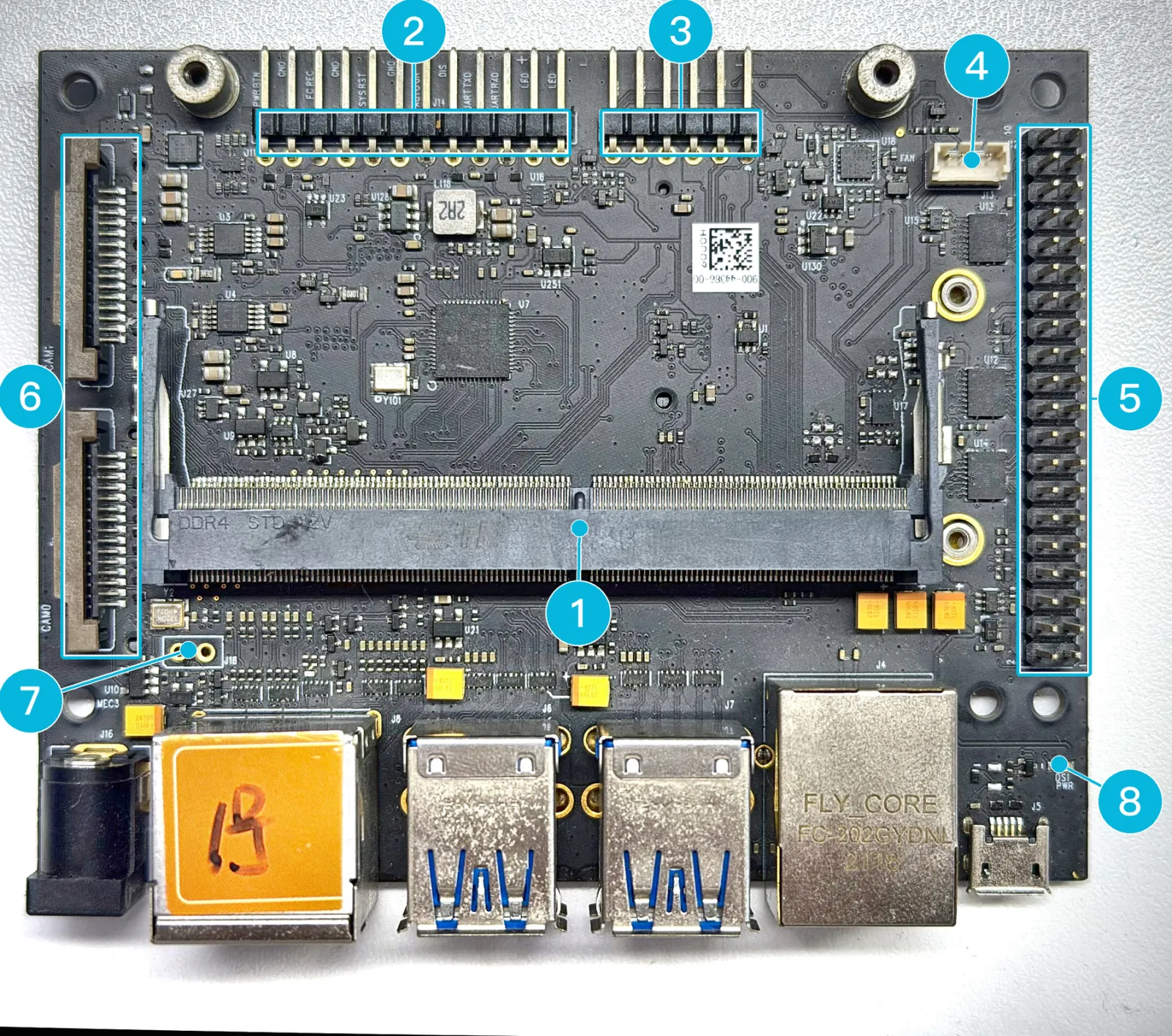
Figure 2. Top side
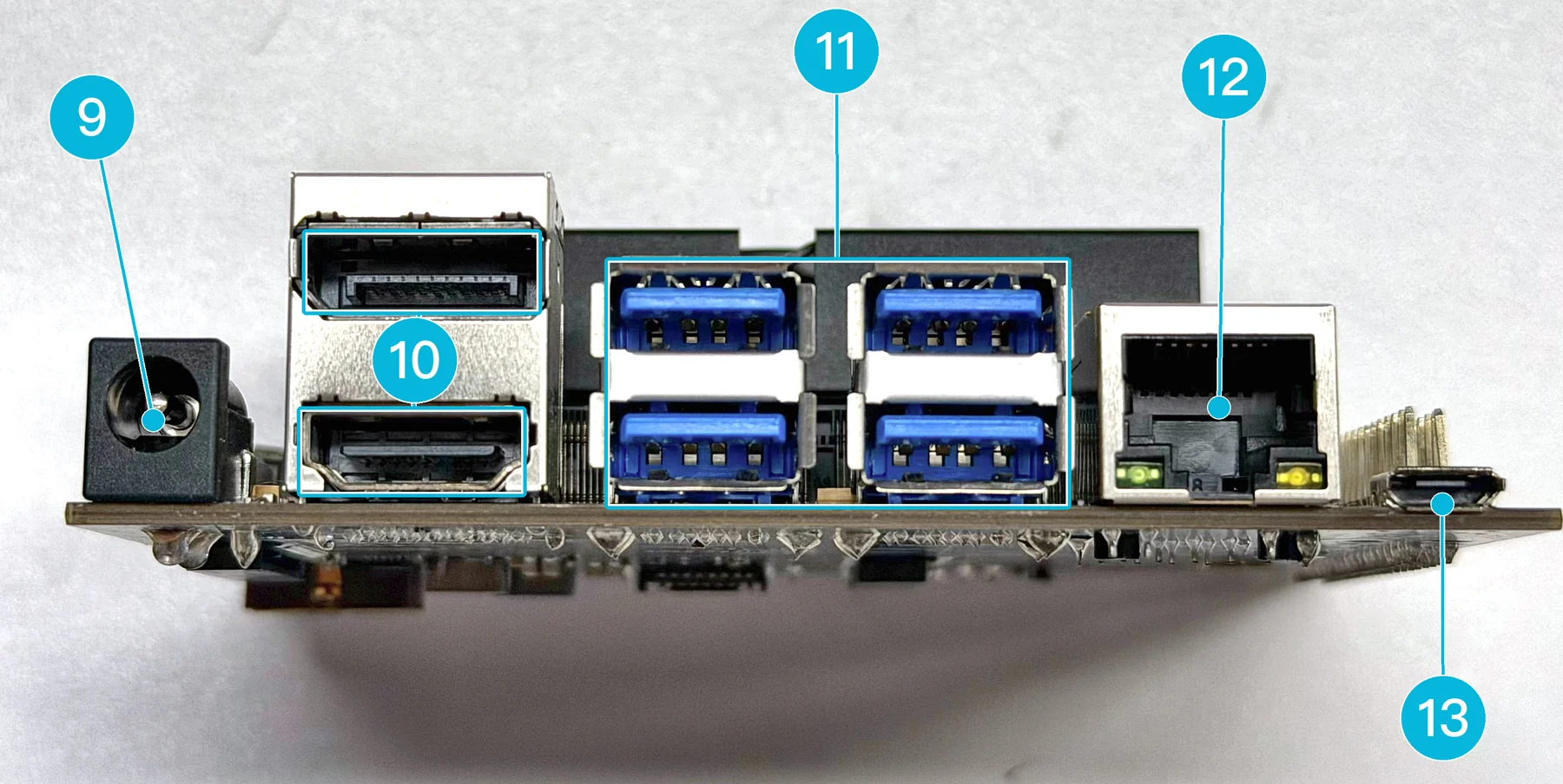
Figure 3. Rear edge
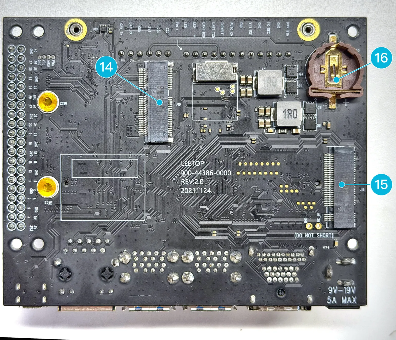
Figure 4. Bottom side
| # | Connector | What it is for |
|---|---|---|
| 1 | SO-DIMM socket | Holds the module |
| 2 | Button header | Debug UART, power button and reset |
| 3 | CAN header | CAN bus |
| 4 | Fan header | Heatsink fan, 5 V PWM |
| 5 | 40-pin header | UART, I²C, SPI, I²S and GPIO, at 3.3 V |
| 6 | 2 x CSI camera, CAM0 and CAM1 | MIPI CSI cameras |
| 7 | PoE header | Optional Power over Ethernet module |
| 8 | Power LED | Blinks once the system is running |
| 9 | DC power jack | Power input, 9 V to 19 V DC |
| 10 | DP (upper), HDMI (lower) | Monitor |
| 11 | 4 x USB 3.0 | Keyboard, mouse, storage and other USB devices |
| 12 | Ethernet | Gigabit Ethernet |
| 13 | Micro-USB, J5 | Flashing an OS image |
| 14 | M.2 Key E, J10 | Wi-Fi and Bluetooth card |
| 15 | M.2 Key M, J11 | NVMe SSD |
| 16 | RTC battery holder | Backup battery for the RTC, CR1225 |
The carrier board also has a microSD card slot. Which interfaces an operating system sets up depends on that system; for Mixtile OS, see Interfaces in Mixtile OS.
Dimensions
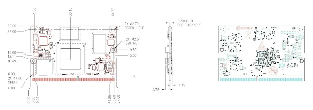
Figure 5. Dimensions of Core 3588E, in millimetres
The module measures 69.6 x 45 mm, the size of the Jetson TX2 NX, and the board is 1.2 mm thick. The two 2.7 mm screw holes, at the corners opposite the edge connector, fix it to the carrier board. The two M2.5 nuts on the module hold the heatsink.