40-pin Header
Carrier boards for the Jetson TX2 NX have a 40-pin expansion header with UART, I²C, SPI, I²S and GPIO signals from the module, and 3.3 V and 5 V supply pins. On the Leetop A206, it is the 2 x 20 header along the right edge of the top side. Seen from above with the USB ports at the bottom, pin 1 is the outer pin at the end nearest the power LED.
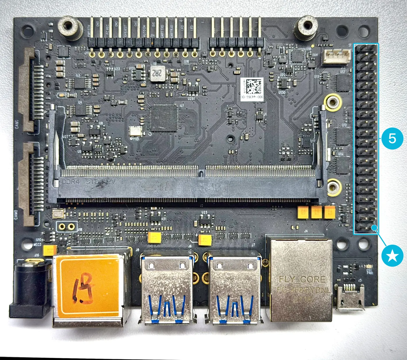
Figure 1. The 40-pin header on the Leetop A206. The star marks pin 1.
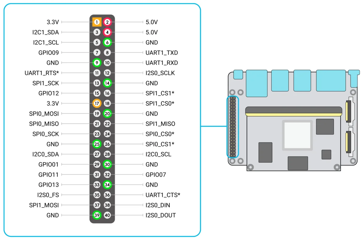
Figure 2. Pinout of the 40-pin header
The signal voltage of the header is set by the carrier board. On the Leetop A206, all signals are 3.3 V. On another carrier board, check its documentation before you connect a device, and do not connect a device that uses a higher voltage.
Pin Assignments
The pin assignment below is part of the hardware. The device names and commands in the UART, I²C and GPIO sections are for Mixtile OS.
The names are the signal names of the module. For their pins on the edge connector, see 260-pin Connector.
| Function | Pin | Pin | Function |
|---|---|---|---|
| 3.3 V | 1 | 2 | 5 V |
| I2C1_SDA | 3 | 4 | 5 V |
| I2C1_SCL | 5 | 6 | GND |
| GPIO09 | 7 | 8 | UART1_TXD |
| GND | 9 | 10 | UART1_RXD |
| UART1_RTS* | 11 | 12 | I2S0_SCLK |
| SPI1_SCK | 13 | 14 | GND |
| GPIO12 | 15 | 16 | SPI1_CS1* |
| 3.3 V | 17 | 18 | SPI1_CS0* |
| SPI0_MOSI | 19 | 20 | GND |
| SPI0_MISO | 21 | 22 | SPI1_MISO |
| SPI0_SCK | 23 | 24 | SPI0_CS0* |
| GND | 25 | 26 | SPI0_CS1* |
| I2C0_SDA | 27 | 28 | I2C0_SCL |
| GPIO01 | 29 | 30 | GND |
| GPIO11 | 31 | 32 | GPIO07 |
| GPIO13 | 33 | 34 | GND |
| I2S0_FS | 35 | 36 | UART1_CTS* |
| SPI1_MOSI | 37 | 38 | I2S0_DIN |
| GND | 39 | 40 | I2S0_DOUT |
UART
UART1 is on pins 8 (TXD) and 10 (RXD), with its RTS and CTS lines for hardware flow control on pins 11 and 36. In Mixtile OS, it is /dev/ttyS1.
To test it with your computer, connect a USB to TTL converter: its GND to pin 6, its TXD to pin 10 and its RXD to pin 8.
-
On your computer, open the converter at 115200 baud, as described in Connect to Core 3588E, with
115200in place of1500000. -
On Core 3588E, install picocom and open the UART at the same speed:
Core 3588Esudo apt updatesudo apt install -y picocompicocom -b 115200 /dev/ttyS1 -
Type in one window.
Expected result: what you type on one side appears on the other. To close picocom, press Ctrl+A, then Ctrl+X.
The user mixtile is in the dialout group, so it can open /dev/ttyS1 without sudo.
I²C
The header has two I²C buses:
| Bus | Pins | Device in Mixtile OS |
|---|---|---|
| I2C1 | 3 (SDA), 5 (SCL) | /dev/i2c-1 |
| I2C0 | 27 (SDA), 28 (SCL) | /dev/i2c-0 |
I2C0 is shared with the real-time clock on the module, at address 0x51. Do not connect a device with the same address to it.
To find the address of a device, connect its SDA, SCL, GND and supply pins, then scan the bus. For a device on pins 3 and 5:
i2cdetect -y 1
Expected result: the table shows the device's address, for example 3c for a common OLED display. The user mixtile is in the i2c group, so the I²C tools do not need sudo.
GPIO
Six header pins have named GPIO lines in Mixtile OS, so you can use them without looking up the GPIO chip and line number:
| Header pin | Signal | Line name |
|---|---|---|
| 7 | GPIO09 | PIN_07 |
| 15 | GPIO12 | PIN_15 |
| 29 | GPIO01 | PIN_29 |
| 31 | GPIO11 | PIN_31 |
| 32 | GPIO07 | PIN_32 |
| 33 | GPIO13 | PIN_33 |
Control them with the gpioget and gpioset tools, run with sudo:
- Ubuntu 24.04 and later, Debian 13
- Debian 12
Read pin 7:
sudo gpioget PIN_07
Set pin 7 high. The pin stays high until you press Ctrl+C:
sudo gpioset PIN_07=1
Read pin 7:
sudo gpioget $(sudo gpiofind PIN_07)
Set pin 7 high. The pin stays high until you press Ctrl+C:
sudo gpioset --mode=signal $(sudo gpiofind PIN_07)=1
To list all named lines, run sudo gpioinfo | grep PIN_.