MIPI CSI
Core 3588E has five MIPI CSI-2 camera inputs on its edge connector:
| Input | Lanes | Can combine to |
|---|---|---|
| CSI0, CSI1 | Two lanes each | One four-lane input |
| CSI2, CSI3 | Two lanes each | One four-lane input |
| CSI4 | Four lanes | — |
Each camera also needs the camera I²C bus, CAM_I2C, and a clock and power-down signal: CAM0_MCLK and CAM0_PWDN for the first camera, CAM1_MCLK and CAM1_PWDN for the second. The pins of all camera signals are in 260-pin Connector.
The current Mixtile OS image does not set up a camera by default.
Camera connectors on the Leetop A206
The Leetop A206 has two 15-pin camera connectors with a 1 mm pitch, next to the SO-DIMM socket. They take two-lane camera modules with a 15-pin ribbon cable, such as modules with the Sony IMX219 sensor.
| Connector | Module input |
|---|---|
| CAM0 | CSI0 |
| CAM1 | CSI2 |
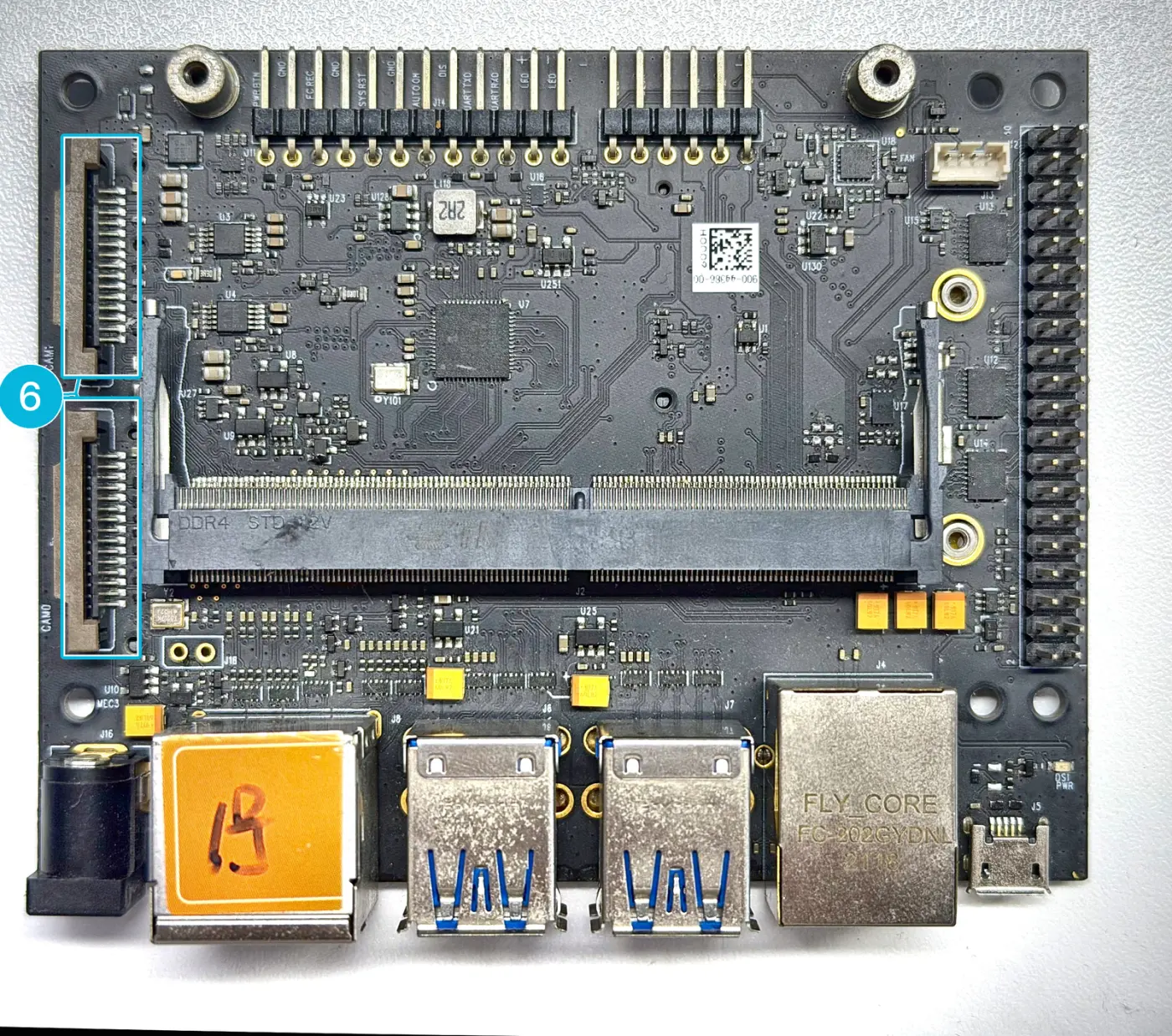
Figure 1. The camera connectors on the Leetop A206: CAM1 above, CAM0 below
Connect a camera module
Connect the camera with the carrier board powered off.
-
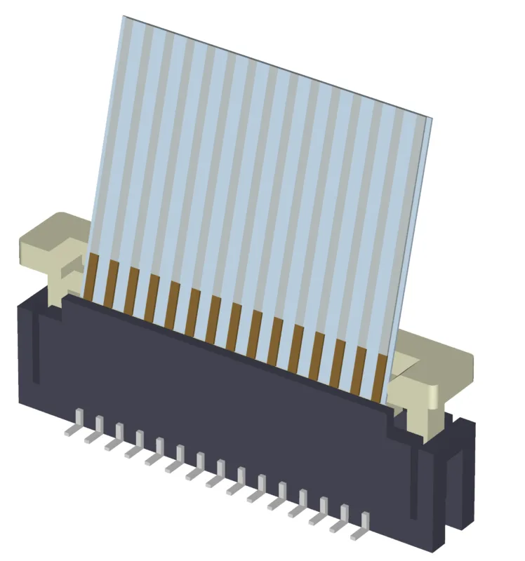
Gently lift the latch of the connector.

-
Insert the ribbon cable with its contacts facing the contacts in the connector.
-
Push the latch back into place, pressing evenly at both ends. Do not use excessive force.
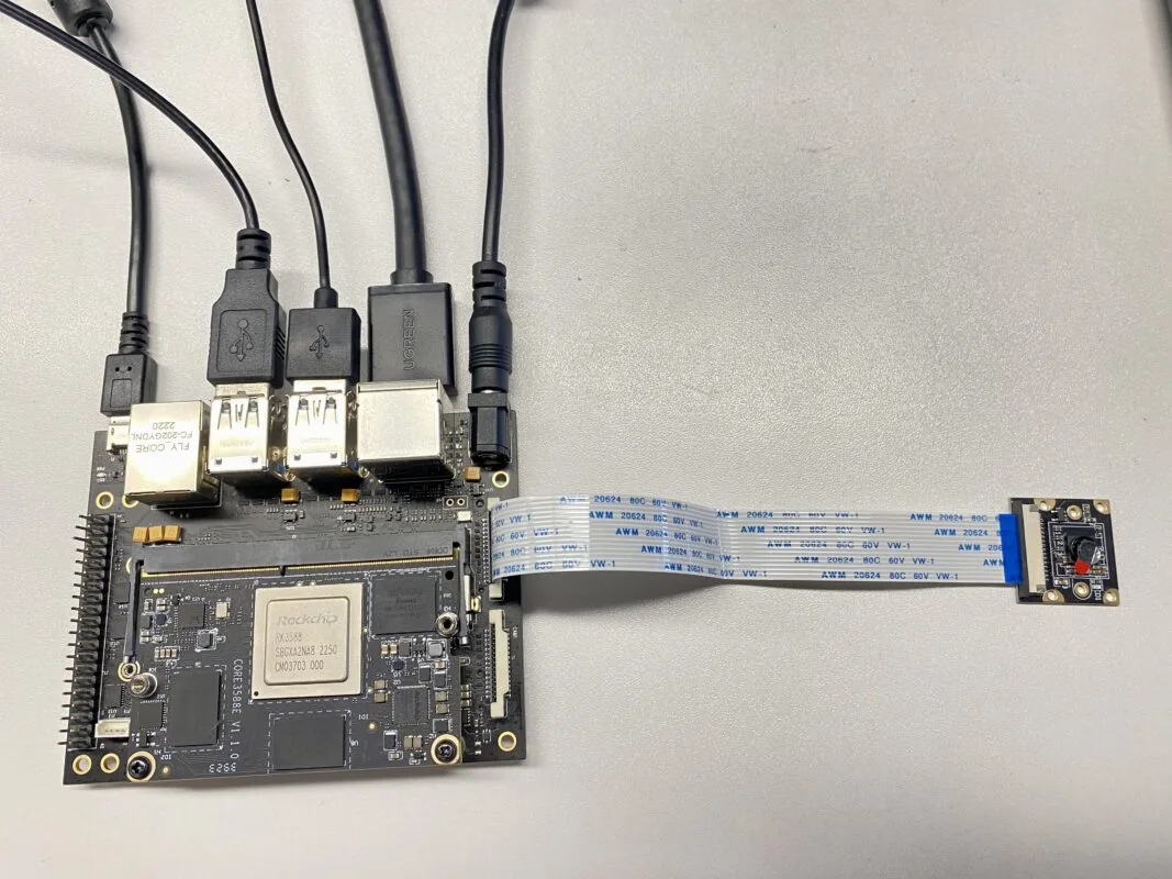
Figure 2. A camera module connected to the carrier board