Hardware Information
This page is the hardware reference for Edge 2: its main components and where each connector sits. For the details of a specific connector, including its pin assignments and how to use it, see the corresponding page in Hardware Usage.
For the full specifications, see Key Parameters.
Block Diagram
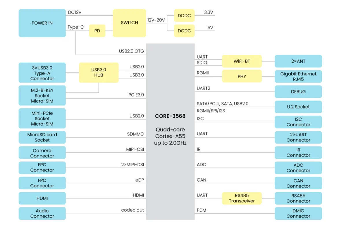
Figure 1. System block diagram of Edge 2
Interface Information
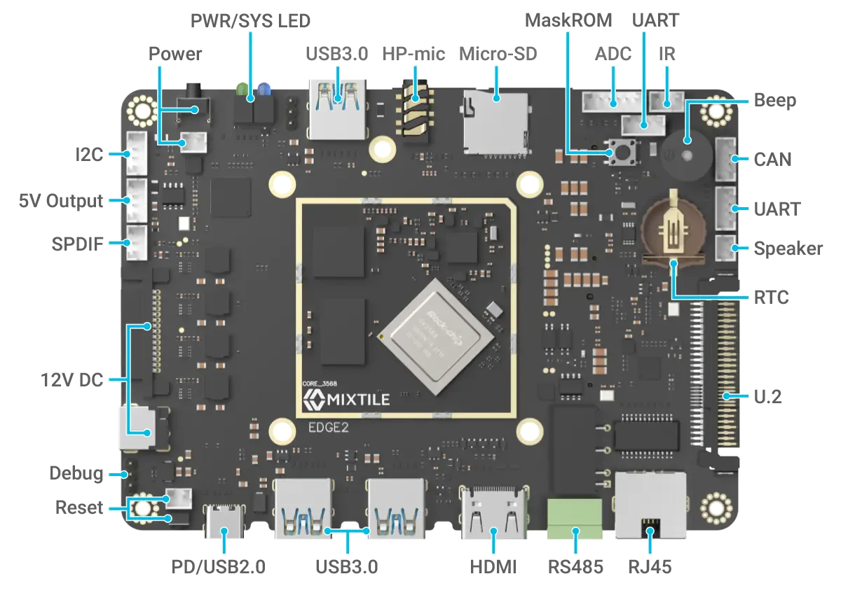
Figure 2. Top side
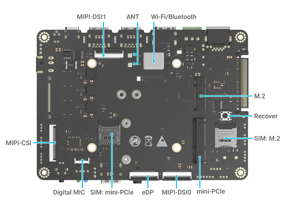
Figure 3. Bottom side
In the table, the port edge is the long edge with HDMI and Ethernet, and the opposite edge is the long edge with the microSD slot.
| Interface | Qty | Location | Description |
|---|---|---|---|
| Mixtile Core 3568 | 1 | Top | System-on-module with the RK3568, memory and eMMC |
| Debug UART | 1 | Top | Three-pin serial console header |
| UART | 2 | Top | UART3 and UART5, four-pin 3.3 V connectors |
| RS-485 | 1 | Port edge | Isolated, three-pin terminal block |
| CAN | 1 | Top | Four-pin connector for an external CAN transceiver |
| M.2 and Mini PCIe | 1 each | Bottom | M.2 Key B with PCIe 3.0 x2 and USB 2.0; Mini PCIe with USB 2.0; a SIM slot for each |
| Display and camera connectors | 4 | Bottom | eDP, MIPI-DSI0, MIPI-DSI1 and MIPI-CSI |
| U.2 | 1 | Short edge | SATA, PCIe 2.0, RGMII and USB 2.0 |
| RTC battery | 1 | Top | Coin-cell holder for the HYM8563 real-time clock |
| Other connectors | – | Top and bottom | I²C, ADC, IR, 5 V output, audio, power and reset button connectors |
| HDMI | 1 | Port edge | HDMI 2.0 output |
| Gigabit Ethernet | 1 | Port edge | RJ45 |
| USB 3.0 Type-A | 3 | Port edge (2), opposite edge (1) | 5 V at 1 A per port |
| USB-C, POWER | 1 | Port edge, at the corner | Power input, and USB 2.0 for flashing |
| DC 12V jack | 1 | Short edge | 12 V power input |
| SATA power connector | 1 | Short edge, next to the DC jack | 12 V power input, or power for a SATA drive on the U.2 connector |
| microSD card slot | 1 | Opposite edge | SD 3.0 |
| Headphone jack | 1 | Opposite edge | 3.5 mm, CTIA |
| Wi-Fi and Bluetooth | 1 | Bottom | AP6275S module, with two antenna connectors marked ANT |
Buttons and LEDs
| Item | Where | Function |
|---|---|---|
| Power button | Opposite edge, at the corner | Starts the board when it is off |
| RESET | Top side, next to the POWER USB-C port | Restarts the board |
| MASKROM | Top side of the board | Held at power-on, starts MaskROM mode for flashing |
| RECOVERY | Bottom side of the board | Connected to a GPIO of the SoC; its function depends on the operating system |
| Power LED, green | Opposite edge, next to the power button | Lights up when the board is powered |
| System LED, blue | Opposite edge, next to the power LED | Driven by a GPIO of the SoC; its pattern depends on the operating system |
For how Mixtile OS uses the RECOVERY button and the system LED, see Hardware Interfaces in Mixtile OS.
Dimensions
The board is 100 x 140 mm. For the Edge 2 Kit enclosure, see Accessories.