M.2 and Mini PCIe
Edge 2 has two module sockets on the bottom side of the board, each with its own micro-SIM slot:
- An M.2 Key B socket, for 4G and 5G modems, NVMe SSDs and other PCIe or USB modules
- A Mini PCIe socket, for USB modules such as 4G modems, LoRa concentrators and the Mixtile Zigbee and Z-Wave module
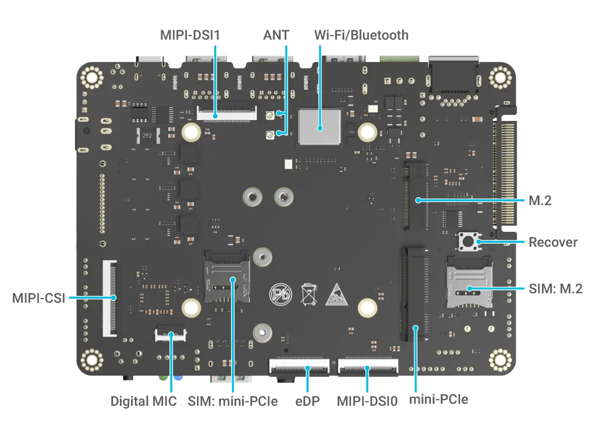
Figure 1. The M.2 and Mini PCIe sockets and their SIM slots, on the bottom side
Specifications
| M.2 | Mini PCIe | |
|---|---|---|
| Socket | 75-pin, Key B | 52-pin |
| Module sizes | 2242, 3042 and 3052 | Full size |
| Interfaces | PCIe 3.0 x2, USB 2.0 | USB 2.0 |
| SIM slot | Micro-SIM, marked SIM: M.2 | Micro-SIM, marked SIM: mini-PCIe |
| Module supply | 3.8 V, up to 3 A shared by both sockets | 3.8 V, up to 3 A shared by both sockets |
The Mini PCIe socket carries no PCIe signals, so it only accepts modules that use USB.
The second PCIe lane of the M.2 socket can also be routed to USB 3.0, for modems that need it. A switch on the board, controlled by a GPIO of the SoC, selects between the two. For the setting used by Mixtile OS, see Hardware Interfaces in Mixtile OS.
Pin Assignments
The tables list only the pins that are connected. All other pins are not connected.
M.2
| Pin# | PinName | PinType | Input/Output | Signal Description |
|---|---|---|---|---|
| 2, 4, 70, 72, 74 | 3.8V | Power | Output | Module supply, 3 A maximum in total |
| 3, 5, 11, 27, 33, 39, 45, 51, 57, 71, 73 | GND | Power | NA | Power and signal reference ground |
| 6 | M2_ONOFF_GPIO1_D2 | signal | Output | Module on or off |
| 7 | HUB_HOST3_DP | USB | BI | USB 2.0 data, positive |
| 9 | HUB_HOST3_DM | USB | BI | USB 2.0 data, negative |
| 10 | M2_LED1 | signal | Input | Network status LED, active low |
| 23 | M2_WAKE_GPIO0_B7 | signal | Input | Module wakes the CPU |
| 29 | PCIE30_TX1_N / HUB_USB3_SSTXN | PCIe | Output | PCIe 3.0 lane 1 or USB 3.0, transmit, negative |
| 30 | M2_UIM_RESET | signal | Input | SIM reset |
| 31 | PCIE30_TX1_P / HUB_USB3_SSTXP | PCIe | Output | PCIe 3.0 lane 1 or USB 3.0, transmit, positive |
| 32 | M2_UIM_CLK | signal | Input | SIM clock |
| 34 | M2_UIM_DATA | signal | Input | SIM data |
| 35 | PCIE30_RX1N / HUB_USB3_SSRXN | PCIe | Input | PCIe 3.0 lane 1 or USB 3.0, receive, negative |
| 36 | M2_UIM_PWR | signal | Input | SIM power |
| 37 | PCIE30_RX1P / HUB_USB3_SSRXP | PCIe | Input | PCIe 3.0 lane 1 or USB 3.0, receive, positive |
| 41 | PCIE30_TX0_N | PCIe | Output | PCIe 3.0 lane 0, transmit, negative |
| 43 | PCIE30_TX0_P | PCIe | Output | PCIe 3.0 lane 0, transmit, positive |
| 47 | PCIE30_RX0N | PCIe | Input | PCIe 3.0 lane 0, receive, negative |
| 49 | PCIE30_RX0P | PCIe | Input | PCIe 3.0 lane 0, receive, positive |
| 50 | PCIE30X2_PERSTN_M1 | signal | Output | PCIe reset |
| 52 | PCIE30X2_CLKREQN_M1 | signal | Input | PCIe clock request |
| 53 | CLK0N_CON | PCIe | Output | PCIe 100 MHz reference clock, negative |
| 54 | PCIE30X2_WAKEN_M1 | signal | Input | PCIe wake |
| 55 | CLK0P_CON | PCIe | Output | PCIe 100 MHz reference clock, positive |
| 66 | M2_SIM_DETECT | signal | Output | SIM card detect |
| 67 | M2_RESET_GPIO3_B5 | signal | Output | Module reset |
| 68 | CLK32K_OUT0 | signal | Output | 32.768 kHz clock |
Mini PCIe
| Pin# | PinName | PinType | Input/Output | Signal Description |
|---|---|---|---|---|
| 1 | WAKEUP_MINIPCIE_GPIO0_C1 | signal | Input | Module wakes the CPU |
| 2, 24, 39, 41, 52 | 3.8V | Power | Output | Module supply, 3 A maximum in total |
| 4, 9, 15, 18, 21, 26, 27, 29, 34, 35, 40, 50 | GND | Power | NA | Power and signal reference ground |
| 8 | UIM_PWR | Power | Input | SIM power |
| 10 | UIM_DATA | signal | Input | SIM data |
| 12 | UIM_CLK | signal | Input | SIM clock |
| 14 | UIM_RESET | signal | Input | SIM reset |
| 22 | MiniPCIE_reset_GPIO3_D4 | signal | Output | Module reset |
| 36 | USB2_HOST2_DM | USB | BI | USB 2.0 data, negative |
| 38 | USB2_HOST2_DP | USB | BI | USB 2.0 data, positive |
| 42 | LED | signal | Input | Status LED |
| 44 | SIM_DETECT | signal | Output | SIM card detect |
Install a Module
- Shut down Edge 2 and disconnect the power supply.
- Turn the board over. The sockets are on the bottom side. If the board is in the Edge 2 Kit enclosure, remove the bottom cover, see Edge 2 Kit Enclosure.
- If the module uses a SIM card, insert the micro-SIM into the slot for that socket.
- Line up the notch in the module's edge with the key in the socket, and insert the module at an angle.
- Press the module down flat, and secure it with the screw.
- If the module has antenna connectors, connect the antennas before you use the module.
- Reconnect the power supply.
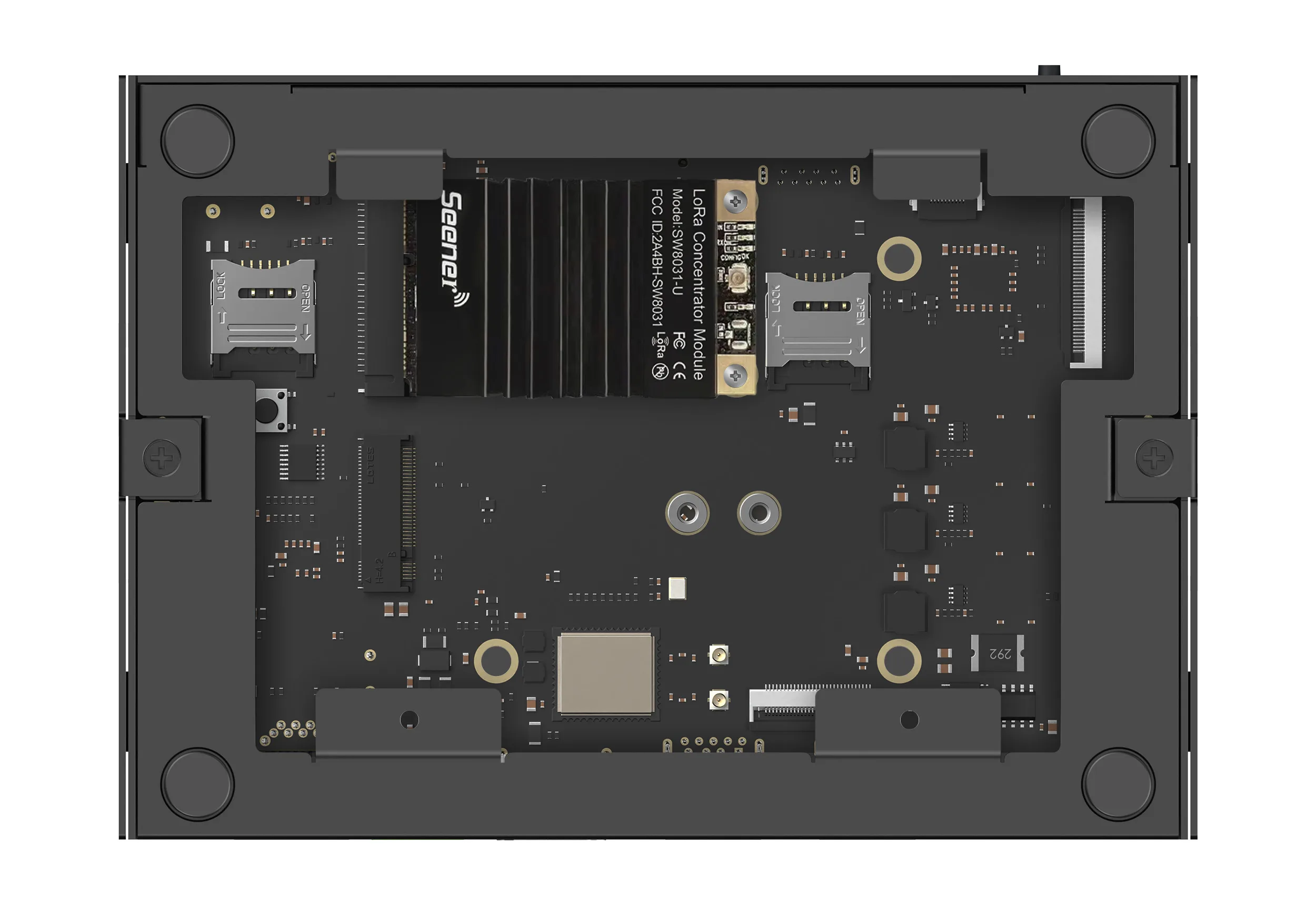
Figure 2. A module installed in the Mini PCIe socket
Verify the Module
Log in to the board, see Connect to Edge 2, and check that the module is listed:
-
A module that uses PCIe, such as an NVMe SSD, appears in the output of
lspci:Edge 2lspciAn NVMe SSD also appears as
/dev/nvme0n1in the output oflsblk. -
A module that uses USB, such as most modems and the Mini PCIe modules, appears in the output of
lsusb:Edge 2lsusb
To work, the module also needs a Linux driver and, for many modules, firmware and user-space software in the running system.
Modules Tested with Earlier Systems
Mixtile tested the following modules on Edge 2 with its earlier Android and Debian 11 images. They have not been tested with Mixtile OS.
| Socket | Module |
|---|---|
| M.2 | Quectel EM06-A (4G), Quectel RM500Q-AE (5G), Western Digital PC SN520 NVMe SSD |
| Mini PCIe | Quectel EC25 (4G), RAK5146 LoRa concentrator |