U.2
The U.2 connector is a 68-pin SFF-8639 connector on the short edge of the board, opposite the DC jack. It carries interfaces for expansion boards:
- Two SATA 3.0 channels, SATA0 and SATA2. The SATA2 lanes can carry PCIe 2.0 instead.
- An RGMII interface to the second Ethernet controller, GMAC0, for an external Ethernet PHY
- A USB 2.0 port
- I²C3
- 5 V, up to 3 A
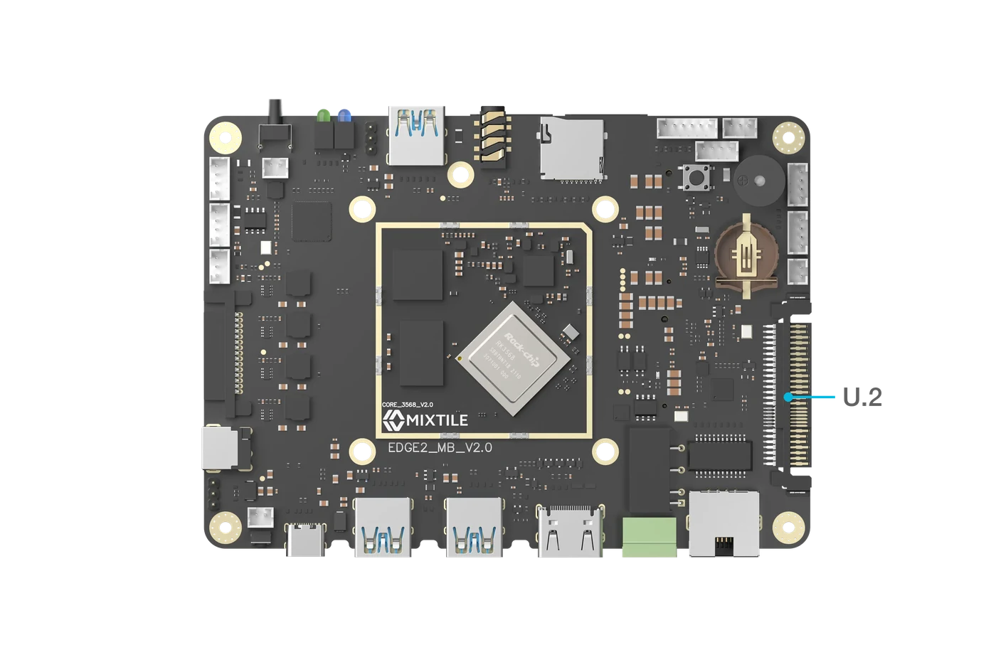
Figure 1. The U.2 connector
The U.2 connector is intended for custom expansion boards. Using its interfaces needs support in the operating system. For the status in Mixtile OS, see Hardware Interfaces in Mixtile OS.
The SATA power connector, on the opposite short edge next to the DC jack, supplies a SATA drive attached through the U.2 connector, and can also power the board, see Power Supply.
Pin Assignments
| Pin# | PinName | PinType | Input/Output | Signal Description |
|---|---|---|---|---|
| 1 | GND | GND | NA | Power and signal reference ground |
| 2 | SATA0_SSRXP | LVDS | Input | SATA data signal input Positive |
| 3 | SATA0_SSRXN | LVDS | Input | SATA data signal input Negative |
| 4 | GND | GND | NA | Power and signal reference ground |
| 5 | SATA0_SSTXN | LVDS | Output | SATA data signal output Negative |
| 6 | SATA0_SSTXP | LVDS | Output | SATA data signal output Positive |
| 7 | GND | GND | NA | Power and signal reference ground |
| 8 | GMAC0_TXEN | IO | Output | RGMII signal |
| 9 | GMAC0_RXD2 | IO | Input | RGMII signal |
| 10 | NC | NA | NA | Not connected to this pin |
| 11 | GMAC0_RXD3 | IO | Input | RGMII signal |
| 12 | GMAC0_RXD0 | IO | Input | RGMII signal |
| 13 | GMAC0_RXD1 | IO | Input | RGMII signal |
| 14 | NC | NA | NA | Not connected to this pin |
| 15 | I2C3_SCL_M0 | IO | Output | I2C clock signal |
| 16 | I2C3_SDA_M0 | IO | I/O | I2C data signal |
| 17 | GND | GND | NA | Power and signal reference ground |
| 18 | GND | GND | NA | Power and signal reference ground |
| 19 | GND | GND | NA | Power and signal reference ground |
| 20 | 5V | PWR | Output | 5V @ 3A Max |
| 21 | 5V | PWR | Output | 5V @ 3A Max |
| 22 | 5V | PWR | Output | 5V @ 3A Max |
| 23 | GND | GND | NA | Power and signal reference ground |
| 24 | NC | NA | NA | Not connected to this pin |
| 25 | GND | GND | NA | Power and signal reference ground |
| 26 | NC | NA | NA | Not connected to this pin |
| 27 | NC | NA | NA | Not connected to this pin |
| 28 | NC | NA | NA | Not connected to this pin |
| 29 | SATA0_LED | IO | Output | SATA0 status for LED |
| 30 | SATA2_LED | IO | Output | SATA2 status for LED |
| 31 | GMAC0_MCLKINOUT | IO | I/O | CLOCK output 125MHz for GMAC0 |
| 32 | GND | GND | NA | Power and signal reference ground |
| 33 | ETH0_REFCLKO_25M | IO | Output | CLOCK output 25MHz for GMAC0 |
| 34 | GMAC0_MDIO | IO | I/O | GMAC management interface data |
| 35 | GND | GND | NA | Power and signal reference ground |
| 36 | GMAC0_MDC | IO | Output | GMAC management interface clock |
| 37 | GMAC0_RXDV_CRS | IO | Input | RGMII signal |
| 38 | GND | GND | NA | Power and signal reference ground |
| 39 | NC | NA | NA | Not connected to this pin |
| 40 | NC | NA | NA | Not connected to this pin |
| 41 | GND | GND | NA | Power and signal reference ground |
| 42 | NC | NA | NA | Not connected to this pin |
| 43 | NC | NA | NA | Not connected to this pin |
| 44 | GND | GND | NA | Power and signal reference ground |
| 45 | USB2_USB3_DM | LVDS | I/O | USB2.0 data signal Negative |
| 46 | USB2_USB3_DP | LVDS | I/O | USB2.0 data signal Positive |
| 47 | GND | GND | NA | Power and signal reference ground |
| 48 | GMAC0_RSTN_GPIO2_D3 | IO | Output | RGMII signal |
| 49 | GMAC0_INT/PMEB_GPIO2_D2 | IO | Input | RGMII signal |
| 50 | GND | GND | NA | Power and signal reference ground |
| 51 | GMAC0_RXCLK | IO | Output | RGMII signal |
| 52 | GND | GND | NA | Power and signal reference ground |
| 53 | GMAC0_TXD3 | IO | Output | RGMII signal |
| 54 | GMAC0_TXD2 | IO | Output | RGMII signal |
| 55 | GND | GND | NA | Power and signal reference ground |
| 56 | GMAC0_TXD1 | IO | Output | RGMII signal |
| 57 | GMAC0_TXD0 | IO | Output | RGMII signal |
| 58 | GND | GND | NA | Power and signal reference ground |
| 59 | GMAC0_TXCLK | IO | Output | RGMII signal |
| 60 | GND | GND | NA | Power and signal reference ground |
| 61 | SATA2_TXN | LVDS | Output | SATA data signal output Negative |
| 62 | SATA2_TXP | LVDS | Output | SATA data signal output Positive |
| 63 | GND | GND | NA | Power and signal reference ground |
| 64 | SATA2_RXN | LVDS | Input | SATA data signal Input Negative |
| 65 | SATA2_RXP | LVDS | Input | SATA data signal Input Positive |
| 66 | GND | GND | NA | Power and signal reference ground |
| 67 | PCIE20_REFCLKN | LVDS | Output | PCIE2.0 reference clock Negative |
| 68 | PCIE20_REFCLKP | LVDS | Output | PCIE2.0 reference clock Positive |
SATA power connector
On the SATA power connector, pins 13 to 15 carry 12 V and pins 10 to 12 are ground.